

An Avionics System of EPIC Proportions
Welcome back to the second part of my series on “An Avionics System of EPIC Proportions.” Although the Honeywell Primus EPIC system is found on many fixed-wing aircraft, to date, the only helicopter platform it is installed on is the AW-139. As discussed in our February/March issue, the Primus EPIC system on the AW-139 employs a distributive architecture.
Part one was an introduction to that architecture and a discussion on the system’s major LRUs. This second part on the Primus EPIC system discusses the major subsystems of the system. All photos and diagrams shown are courtesy of AgustaWestland.
The key subsystems are:
• Automatic flight control system (AFCS)
• Communications
• Indicating and recording
• Navigation
• Flight management system (FMS)
• Attitude heading reference system (AHRS)
• Weather radar
• Radio altimeter
• Central maintenance system
Automatic Flight Control System (AFCS)
The AFCS installed in the AW-139 can have an autopilot, yaw damper and flight director. In fact, this is a dual system in that there are two autopilots, two yaw dampers and one flight director. A second flight director is an available option.
Under normal flight operations, both autopilots and yaw dampers are active at the same time. Honeywell refers to this as an “active-active” system. Both autopilots and yaw dampers drive their own actuators to provide complete control throughout the helicopter’s flight envelope. A single fault/failure of any LRU/module will cause the dual system to transfer complete control to the side that does not have the fault/failure and continue to operate.
All flight director (FD) modes remain engaged as does the autopilot and yaw damper. The ability to detect and annunciate a failure, transfer operation from both systems to the remaining good system, keep the flight director modes engaged and the remaining autopilot active is called “fail-operational.” The AFCS software is housed in modules located in the modular avionics units (MAUs.)
AFCS Configurations
The AFCS for the AW-139 is available to the end user in three configurations:
Basic three-axis system – This provides basic autopilot and stability augmentation system (SAS) functions. It also provides dual pitch, roll, yaw and trim control functions. No flight director is provided. This configuration is suitable for visual flight rules (VFR) operations.
Three-axis system with a two-cue flight director – This configuration provides all of the autopilot and yaw damper functions listed above, along with pitch and roll flight director modes that can be coupled to the autopilot. This configuration is suitable for instrument flight rules (IFR) operations.
Four-axis system with a three-cue flight director – This is the full up configuration that provides all the functions of the three-axis system but adds a servoed collective drive (the fourth axis). It also adds a third cue for the servoed collective. With the installation of the Honeywell flight management system (FMS), the flight director now has the additional capability of flying lateral navigation (LNAV) and vertical navigation (VNAV) commands from the FMS.
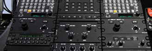
AFCS Controllers
The AFCS in the AW-139 installation utilizes the following controllers:
• Autopilot controller (PC-770)
• Remote instrument controller (RI-553)
• Display controller (DC-840)
• Guidance controller (GC-810)
Autopilot Controller (PC-770)
The single autopilot controller allows the flightcrew to select and control both autopilot systems. The PC-770 enables the flightcrew to select which of the two systems is the “MASTER” system, perform the required pre-flight system test, and couple the FD to the AP. It also allows the flightcrew to select the SAS mode or attitude hold (ATT) mode of operation.

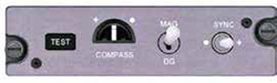
Remote Instrument Controller (RI-553)
The two remote instrument controllers allows selection of selected course, selected heading, and decision height (DH) set for both the pilot and co-pilot’s displays. It also allows for a radio altimeter self-test to be performed. The heading knob has a push direct feature and the course knob has a push sync feature.
Display Controller (DC-840)
The two display controllers are used to select information to be displayed on each PFD. This includes altitude preselect and the BARO setting. The data set on the PFDs is used by some of the FD modes to generate computer steering commands that can be hand flown by the flightcrew or coupled to the autopilot for hands-off flight.
Guidance Controller (GC-810)
The guidance controller is used to select which flight director modes are being actively used, which modes are armed, and to select which PFD navigation source is being used by the flight director (pilot’s or co-pilot’s PFD).
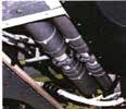
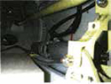
Autopilot/Yaw Damper Linear Actuators (SM-7000)
The muscle for the autopilot is in the form of flight control linear actuators. There are two each flight control linear actuators (smart servos) for the pitch, roll and yaw axes. They are mounted in a serial fashion in the mechanical flight control rigging for each axis. This allows the pilot to fly through the AFCS if need be, and also allows SAS inputs to aid the pilot when hand flying the aircraft. The linear actuators are called smart servos as the actuator drive signal is processed by a microprocessor in the actuator itself.
Communications Systems
In the AW-139, the Honeywell communications package consists of dual VHF communication radios, a selective call (SELCAL) capability, a digital audio system and connections to the cockpit audio system. Links to the cockpit voice recorder (CVR) and cabin PA system are also provided. A high frequency (HF) is an available option and can be mounted as a standalone LRU in the aft avionics bay area. With the HF option, an antenna coupler and high-power amplifier are also required.
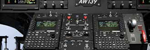
The radio modules are mounted in the pilot’s and co-pilot’s modular radio cabinets (MRCs).
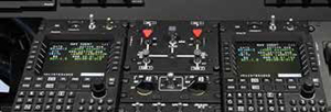
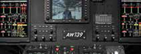
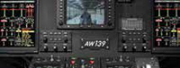
The radios are controlled from the multifunction control display units (MCDU) located at the top of the center pedestal on the flight deck. The NAV radios can also be controlled from the PFDs using the CC-700 cursor control devices (CCD).
Indicating and Recording Systems
In federated and integrated system architecture, many of the indicating and recording functions were accomplished by dedicated LRUs such as data acquisition units (DAUs) for engine data. The engine instruments are no longer individual LRUs, but are electronically displayed as part of the engine indicating crew alerting system (EICAS) display on the MFDs. The aircraft clock was also a standalone LRU, and in many instances system warning and failure events had their own indications on the dedicated failure/warning panel.
In the Primus EPIC system on the AW-139, all of the functions above are tied together and reside on modules in the MAUs. The indications are shown on the PFD, MFD, EICAS or MCDU displays. There are still dedicated master caution/warning lights situated in front of each pilot for particular system annunciations. These lights are tied into the aural warning system and also to the EICAS display.
Navigation Systems
The navigation systems for the Primus EPIC system are quite diverse and range from the flight management system (FMS), to VHF radios and the air data system (ADS).
Flight Management System (FMS)
The FMS has two primary functions and multiple secondary functions. The primary functions are position computation and flight planning. These functions work with the associated FD modes in both the lateral and vertical axes. The navigation database (NDB) contained in the FMS is essential to these functions. The data base is used to store waypoints, navaids, airways, procedures, airports and other navigation data. It is updated on a 28-day cycle.
The FMS connects to a variety of short-range and long-range navigation sensors. The primary short-range sensors are AHRS, DME/DME and VOR/DME. The long-range sensor on the AW-139 is the global positioning system (GPS). Using the available sensors, the FMS develops a position based on a blend or mix of sensor inputs. Based on the position and the flight plan, the FMS generates information for display on the MCDU and EDS.
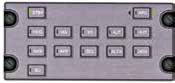
MCDU Color Scheme
For Primus EPIC, Honeywell has replaced the FMS control display unit (CDU) and radio management unit (RMU) with a multi-function control display unit (MCDU). In addition to control of the FMS, the MCDU controls radio tuning and the automatic flight information system (AFIS), with growth capability for control of communications navigation surveillance/air traffic management (CNS/ATM) functions. The FMS software is housed in processor modules in the MAUs.
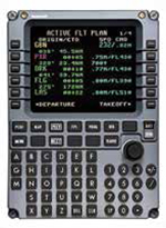
The MCDU is a keyboard control/display unit that provides keyboard entries for the FMS. It features a full-color active matrix liquid crystal display (AMLCD). It also has twelve line select keys to insert or change specific flight data and nine active function keys that provide direct access to specific pages within the FMS application.
One of the important FMS pages that can be called up by a maintenance specialist is the “Maintenance Page.” To select the Maintenance Page, the maintenance specialist pushes the NAV button located below the MCDU screen. This displays the NAV Index Page. Pressing the NEXT button below the MCDU screen displays page two which is shown here.
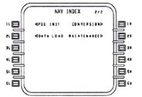
Pressing the line select key (LSK) adjacent to the MAINTENANCE prompt displays the FMS MAINTENANCE PAGE 1/3 shown below. The number 1 or 2 after FMS indicates which FMS is being looked at.
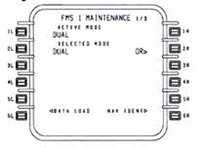
The screen shown indicates that the FMS was selected to be in the DUAL mode and is active in the DUAL mode. If a problem existed, it is possible that the FMS would be active in a mode other than the one selected.
The lateral navigation function of the FMS can calculate navigation information relative to selected geographical points. The pilot can define flight plan routes worldwide.
The FMS allows flight plan building and storage and creating and storing waypoints. The FMS has three databases associated with it.
• Navigation database
• Custom database
• Aircraft database
The navigation database contains information on navigation aids (NAVAIDS) and earth reference points such as airports, runways, intersections and routes.
The custom database is where the flightcrew build and store flight plans, waypoints, holding patterns, etc.
The aircraft database allows the VNAV portion of the FMS learn how the pilot is flying the helicopter, and makes adjustments to help determine top of climb (TOC) and top of descent (TOD) points.
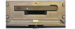
Data Management Unit (DMU)
Lastly we come to the DMU. This LRU is an option for the Primus EPIC system on the AW-139 helicopter. The DMU can be used to enter or retrieve data from the aircraft in normal operation. It can be used to upload all FMS operational databases discussed earlier.
The DMU is a combination DVD/CD-ROM read-only drive and dual flash memory module ports (PCMCIA). This abbreviation stands for Personal Computer Memory Card International Association.
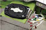
Attitude Heading Reference System (AHRS)
In terms of attitude and heading sensors in the AW-139, the days of a separate displacement type vertical gyro for actual aircraft pitch and roll attitude data, and a displacement type directional gyro for heading information are not required. Instead, the AW-139 employs a laser fiberoptic gyro (FOG) inertial attitude and heading sensor system.
The AHRS rate based fiberoptic gyros provide the helicopter’s actual pitch and roll attitude, magnetic heading and other flight dynamics data to the EDS, FMS and AFCS. The AHRS also provides data for weather radar antenna stabilization, and any other systems that require attitude, heading, rate and accelerometer data.
In addition to the FOGs, the AHRS utilizes micromechanical accelerometers aligned with the aircraft’s primary axes to supply an inertial measuring system. A separate flux valve is used for each system (pilot and copilot), to provide a long term magnetic reference. The air data system (ADS) provides a true airspeed (TAS) input to help in the calculations of pitch and roll attitude. The AHRS can provide inertial altitude and vertical speed data if it receives a pressure altitude input from the ADS. It can also provide true velocity and groundspeed data if it is connected to a GPS receiver.
Primus 660 Weather Radar System (WX)
The weather radar system in the AW-139 helicopter is Honeywell’s Primus 660. The Primus 660 weather radar system is an X-band, four-color, digital radar designed for airborne weather detection and avoidance. The system displays storm intensity levels in bright colors against a black background utilizing the advanced displays installed on the flight deck. The Primus 660 is a high-power (10 KW) system that provides the flight crew with high-confidence, tactical weather avoidance to manage the overall flight of the helicopter.
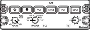
The Primus 660 weather radar system meets the following requirements:
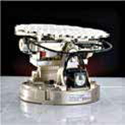
• Combined receiver/transmitter with flat-plate antenna (RTA)
• WU-660 WX radar controller.
Integrated receiver/transmitter antenna (RTA) has a:
• 10 kW transmitter
• 12-inch high-gain flat-plate antenna
• Attitude stabilization
• Provides a four-color display
• Provides five-mile to 300-mile ranges
• Provides enhanced modes and controls:
• Rain echo attenuation compensation technique (REACT)
• Ground mapping (GMAP
• Target alert (TGT)
The Honeywell Primus 700/701 weather radar system is offered as an option on the AW-139 helicopter.
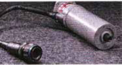
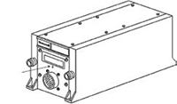
AA-300 Radio Altimeter System (RA)
The RT-300 radio altimeter provides absolute altitude above the terrain or whatever is beneath the helicopter from zero to 2,500 feet. The readout is displayed on both PFDs. The receiver/transmitter (RT) connects to both transmitter and receiver antennas. There is a zero height adjustment on the front of the R/T unit as this unit can be mounted in a variety of aircraft, and the antennas can be at different heights above the ground depending on the aircraft and installation location.
The radio altimeter also provides a trip point for the decision height (DH) annunciation on the PFDs and a low altitude awareness trip point. The radio altimeter also interfaces with TCAS, EGPWS and other systems as required. Interface with the Primus EPIC system is accomplished through the generic I/O modules in the MAUs.
Central Maintenance System (CMS)
From a maintenance perspective, the CMS on the AW-139 helicopter provides a reliable troubleshooting tool to help solve maintenance problems that may arise.
The aircraft diagnostic and maintenance system (ADMS), provides a centralized interface between the aircraft and the maintenance specialist. The ADMS is the next step to the capabilities previously provided by other computer assisted troubleshooting and maintenance systems.
Overall the ADMS consists of two major parts. The first part is the central maintenance computer (CMC). This is a module located in the MAUs. It provides the central interface and collection point for maintenance messages and inquiries. The second part is the aircraft condition and monitoring function (ACMF). The ACMF collects and records aircraft data when certain specified events have occurred.
The CMS is a combination of the CMC and the LRUs/LRMs that make up the “member systems” of the aircraft.
Central Maintenance Aircraft Diagnostic Philosophy
Both AgustaWestland and Honeywell considered the following points in designing and implementing the ADMS on the AW-139 helicopter.
• Information that does not contribute to the performance of effective maintenance should not be displayed.
• Maintenance messages displayed should identify the root cause of the problem.
• The syntax of the messages should be consistent and use simple terminology, keeping in mind that not all operators of the helicopter will have English as their primary language.
• Built-in-test (BIT) information should correspond to pilot reports/alerts. It is unacceptable to alert the flight crew of a fault without telling maintenance specialists what to do about it.
• The logic used to generate maintenance messages should include logic to eliminate cascaded faults.
• The maintenance operation should be simple and intuitive.
I hope that you have enjoyed our two-part overview of the Honeywell Primus EPIC system on the AW-139 aircraft. If you have any questions or would like to receive additional information on the AW-139 aircraft or the Honeywell Primus EPIC system, please contact AgustaWestland through its Web site at www.agustawestland.com.