
Mastering an Astronics Max-Viz Installation
As I travel around the country giving seminars and visiting helicopter maintenance shops, I am increasingly asked how to manage the installation and integration of complex new electronics installations, particularly systems that closely interact and tie in with other systems on the helicopter.
Some shops have this down to a fine science and seem to welcome the challenge of installing every new piece of electronic gear that comes along. Others, however, find dealing with all this new electronic wizardry a daunting task. Maybe they’ve had a bad experience in the past, or perhaps they just aren’t confident with electronic equipment they don’t really understand.
For whatever reasons, shops that are turning away this kind of work are missing good earnings opportunities. In the long run, they risk being left behind in an aviation world that is increasingly reliant on state-of-the-art electronic hardware. The hard truth is that our customers are going to expect us to be able to do this kind of work. The good news is that, properly managed, it isn’t all that difficult.
To illustrate what I’m talking about, in the text and pictures that follow, I’m going to walk us through the installation of an Astronics Max-Viz enhanced vision system (EVS). For those of you not familiar with it, Astronics Max-Viz EVS is an infrared system that lets you see at night or in smoke, haze or light fog. This is high-tech, leading edge stuff. Max-Viz EVS works by detecting variations in the heat signature of various objects. It can be used as an alternative to or in tandem with night vision goggles. Astronics Max-Viz provides real time confirmation of the environment in low visibility situations, so you can see why it’s a must-have feature for many of today’s helicopter operations.
As you follow along with me, we’ll see that the installation of this sophisticated system is not difficult, and is well within the capability of most of today’s helicopter maintenance operations. Astronics Max-Viz EVS comes in two versions, the 600 and 1500 models. The 600 is STC’d and applicable for light piston helicopters like the Robinson R-44, but for most midsize and larger helicopters, most operators are going to want the 1500 model, so that’s the installation we’ll cover here.
For demonstration purposes, we’ll install the EVS 1500 on an Airbus EC-135, which I’ve chosen because they’re pretty common today, and the installation is typical in terms of degree of difficulty and commonality of systems we are likely to encounter. Of course, no two helicopters are ever the same, so even if we’re doing another EC-135, there are likely to be some differences.
The starting point is to acquire the system that is going to be installed. In the case of the Astronics Max-Viz, we’ll go to their Web site (max-viz.com) and make sure there is an STC for the customer’s aircraft. Astronics has more than 200 STCs for both fixed- and rotorwing models, so unless it’s unusual, they probably have what we’ll need.
This part of the process is more complex than just saying, “send me the one for the EC-135.” We’ll need to have a good understanding of the customer’s requirements and his/her aircraft configuration. For example, do they have a requirement for multiple displays? If it’s a VIP aircraft, they might have a dual pilot operation, as well as wanting EVS displayed in the back of the aircraft. If it’s a fire fighting or police surveillance aircraft, they’ll need different displays.
We need to know what kinds of avionics are installed, because there are different STCs for different systems. We’ll also talk about switch configuration. Another important factor is whether the aircraft is going to be exported. With Astronics Max-Viz, we have personnel who will walk you through the process, so it’s not difficult, but it will save you some trouble if you order the right system that is configured for your aircraft upfront.
We’ll also talk about your specific shop capabilities and what your timeframe is (because there’s a lead time for the STC kits) and we’ll discuss the configuration timing to give you an idea of the complexity of the installation so that you can allocate the time for it. From an income perspective, installers can expect anywhere from 20 to 48 shop hours.
So now you’ve ordered your kit, and in four to eight weeks you’ll get a FedEx package with the EVS in one box and all the electrical and structural provisions in the other. The first step now is planning because everything else will flow from that.
You lay out the kit and all the documentation, then inventory the kit to make sure that you’ve got everything. Next you’ll use the drawings or instructions for continued airworthiness (ICA) to separate the equipment into subgroups, the source power subgroup, a cockpit switch subgroup, a power supply and interface subgroup, and a structures subgroup, which could also include a fairings subgroup. I prefer to lay everything out on separate tables so I don’t co-mingle anything.
By establishing all the subgroups, you’ve basically defined a statement of work. Then I prefer to pause and take a look at the aircraft to figure where and how is the most logical way to proceed. Am I doing this myself or doing it as a team? I prefer the team approach because it reduces down time on the aircraft and because many of these tasks can be done in parallel.
The work is basically in two categories: structures and avionics. In a medium helicopter like an EC-135, there’s enough room and enough work for a team of two each for structures work and avionics work.
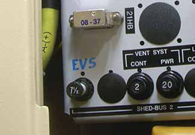
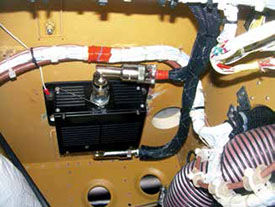
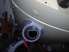
Obviously the helicopter is going to have to be taken apart to a certain extent, depending on the complexity of the aircraft and the actual installation. You might have an avionics technician who starts taking down the circuit breaker panel and opening up the access route for the 28 vDC power supply (Figures 1 and 2).
At the same time, a second avionics technician might be starting to measure and build up one side of each of the cables, so you’ll have the airframe side of the cable which is going be connected to the power supply. Then they can build up one side of the sensor or imager cable, which goes from the power supply to the EVS 1500 sensor. That puts the two avionics technicians working effectively in two different locations.
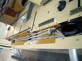
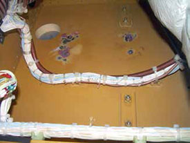
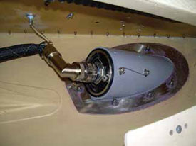
Simultaneously the structures team starts opening up access to begin their part of the installation (Figures 3, 4, 5 and 6). An early step is to install internal doublers where the EVS sensor and fairing will mount. The doubler becomes a guide for locating and cutting the hole. The doubler is attached to the airframe (Figure 7) with a bonding agent that takes eight to 12 hours to cure.
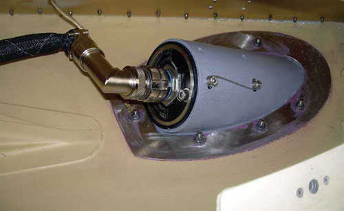
The power supply has to be mounted to the airframe. You can attach it to a bulkhead, or in a helicopter like the EC-135 with a lot of composite structure, you can simply install threaded inserts (Figure 8). These are also bonded and have to cure, and then the power supply and fairing are attached to the inserts (Figure 9). The fairing and sensor are then mounted to the airframe (Figures 10, 11 and 12).
In the meantime, the circuit breakers are installed (Figure 1) and the two technicians working on the electrical installation meet up at the power supply. They then start running all the cabling for the switches. The cabling gets routed and cut, then terminated at the appropriate length, and at that point everything is being connected.
Each STC has a post-installation checklist that is included in the ICA. We perform a basic ops check of the equipment in a specific sequence. Then we do an electromagnetic interference or EMI test, which usually requires two people. We are checking to see whether there is electronic noise in the display. Do we have any noise on the radios, with or without the EVS turned on? I don’t think I’ve ever heard of that, but basically any time we are installing electronic components, we are checking to make sure that none of the existing electronic systems interfere with the EVS, and crosschecking to make sure that the EVS doesn’t impact any of the other systems in the aircraft.
At that point we will normally get a sign off from whoever is inspecting the installation, confirming that all the work is complete and in conformance with the STC. That completes the process.
Some shops might elect to do an installation like this in stages in order to limit how long the aircraft is grounded. For a VIP aircraft, having it unavailable for three or four consecutive days might be unacceptable. We can do a lot of the pre-wiring and configuration work in advance, and then bring the airplane in for a day to complete the structural segment and final installation.
However you choose to do it, installing equipment like an Astronics Max-Viz 1500 enhances a helicopter’s capabilities and provides lucrative work for the shop that maintains it. If your shop isn’t stepping up to this kind of project, you should definitely look into it. It’s easy, profitable, and just what you need to be doing to keep up with the times.
 Bob Yerex is a retired Army and Coast Guard helicopter pilot with more than 8,000 accident-free hours. After retiring as a search and rescue pilot, he flew as a commercial airline pilot for four years, and then two years flying EMS single pilot IFR helicopters. He has also worked as a structures mechanic in the U.S. Marine Corps on electronic warfare jets and C-130 transports and has served as a Part-135 mechanic. Yerex is a graduate of Embry-Riddle Aeronautical University and the Naval Postgraduate School.