
Rotor Blade Track and Balance - Past and Present
Asking seven helicopter maintenance professionals for their insight on rotor blade track and balance is like asking seven sportscasters which is the best college football team … you will get seven different answers. No answers are wrong — they just differ from each other.
Most fixed-wing aircraft are inherently stable. That is, if you place the aircraft in straight and level flight and take your hands off of the controls, the aircraft will pretty much stay where it is. Helicopters, on the other hand, are inherently unstable, and if you put one in straight and level flight and take your hands off the controls, it will undoubtedly try to roll over on its back. A helicopter’s flight dynamics are so different from a fixed-wing aircraft’s that we encounter maintenance issues that are totally unique to helicopters.
Many perceive a helicopter as a conglomeration of rotating parts that, in order to fly, work in unison to beat the air into submission. This is probably not too far from the truth, but the whole concept of rotating parts is where the tracking and balancing of the main rotor blades comes into being. Tail rotors also need to be tracked and balanced, but we are not going to address that in this article.
What is Track and Balance?
I guess a good place to start is to ask the question, “Why do rotor blades need to be tracked and balanced?” Rotor blades travel around a hub at a given speed. In flight, they also change their pitch angle to generate the helicopter’s direction of flight, speed and lift. Ideally, if all the blades are perfectly identical and have been installed exactly to specifications, then for a given cyclic and collective setting, the rotor blade tips will all “track” through the exact same point in space at a given point in the rotation around the hub. If the blades are out of balance, they will cause a vibration or beat frequency that is transmitted into the rotor head, transmission and airframe. This vibration will also be felt in other components on the helicopter. Excessive vibration levels can lead to premature wear and failure in components, and this leads to increased maintenance costs and aircraft downtime.
Balancing of the main rotor system is accomplished in the helicopter’s main rotational frequency. This is expressed as the n-per-rev, where n = the number of blades in the system. A three-bladed rotor system would have an inherent
three-per-rev frequency, a four-bladed system an inherent four-per-rev frequency and a five-bladed system an inherent five-per-rev frequency. When the mechanical condition of the helicopter is suspect, these vibrations can be quite noticeable once the main rotor 1-per-rev vibration is reduced.
Vibrations
Vibrations can be separated into two different types, vertical and lateral. Vertical vibrations can be caused by several different factors, but result in the rotor blades producing unequal lift at a given point in their rotation. This occurs due to slight variations in the manufacturing process that can cause a slight change in blade chord profile, or by the improper adjustment of the pitch change links and blade trim tabs.
Lateral vibrations are caused by the rotor blades being of unequal mass distribution. Again, this can be due to the manufacturing process where there may be slight differences in components.

Other factors that may cause lateral vibrations are improper alignment techniques, assembly procedures, etc. Lateral vibrations can also be induced by a rotor system that is out of vertical balance or out of track.
You would think that to achieve the smoothest possible ride, the ideal goal would be to balance all the main rotor blades exactly the same and have all the blade tips pass through exactly the same point in the rotational plane. Well, the concept is true, but in reality, that does not always lead to the smoothest ride. It is not uncommon for some helicopters to have a smoother ride with what is called a “track split.” That is to say that not all the blade tips pass through the same point in the rotational plane. There is a split in position among the blades. However track and balance is achieved on your helicopter, when the job is done, the helicopter should have the smoothest ride possible.
The Evolution of Tracking Test Equipment
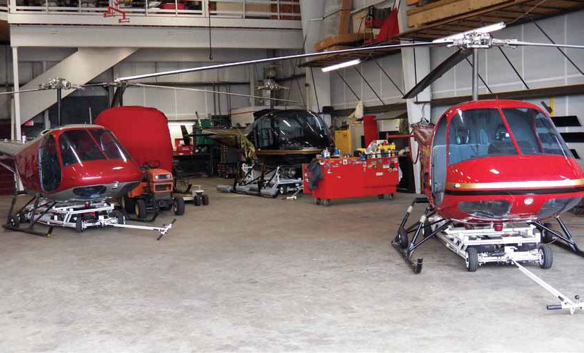
To get some sense of how track and balance techniques have evolved over time, I traveled to Sharkey’s Helicopters in Lebanon, NH. It specializes in Bell and Enstrom helicopters and provides service, parts, charter and flight instruction. Company president Roger Sharkey is well recognized in our industry in performing helicopter track-and-balance maintenance. Sharkey started operations on Oct. 24, 1973. The first aircraft he bought was an ex-army surplus Hiller 12 C. The second aircraft was a Bell 47G and they both had wooden rotor blades. As of this writing, he had eight helicopters for sale: one Bell 407, one Bell 206B3, four Enstrom model 480Bs, one Enstrom model 28F and one Enstrom model F28A. Sharkey and I sat down and he provided me with an interesting one-on-one tutorial on how the mechanics of helicopter rotor blade track-and-balance techniques have evolved over time.
In the Beginning
In BC (before computers) times and the days of wooden rotor blades, helicopter manufacturers and mechanics used what was referred to as “static” balance equipment to achieve rotor system track and balance. This equipment was usually in the form of a balance-beam assembly with a bubble-type level and a set of tracking flags. The static balance device was used to adjust the main rotor span and chord-wise mass distribution. A long, vertically-held pole that had two horizontal arms protruding from it would have multiple pieces of tape (tracking flags) attached between the horizontal arms. The individual main rotor blade tips were coated with differently-colored grease pencil or chalk.
With the helicopter running on the ground, the tracking flags were moved in toward the rotor blade tips. As the blade tips made contact with the flags, each left a mark corresponding to its assigned color. If the marks were vertically separated, a pitch-change adjustment was needed to move the blade tips closer together. If the marks overlapped one another, no adjustment was required. The downside to this method is that it was dangerous and could only be done on the ground.
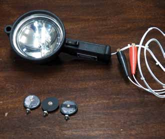 The next step in improving how rotor blade track was accomplished was with a constant light fixture used in conjunction with a sighting tool and reflectors placed on the end of the blades.
The good news about this system is that it was inexpensive to buy and easy to setup. The bad news was that you could only do two main rotor blades at a time and track was perceived. If you had a three- or four-bladed system, then you would track the third and fourth blade to the master blade. Any blade can be the master, but is usually best to pick the lowest-serial-numbered blade. We say that the track of the blades was perceived because there was no scale to measure against. Without a metric, it was up to the individual performing the work to say when perfect track was achieved. There was also no way to balance the rotor blades. Since we, as individuals, can sometimes look at the same thing and see it differently, perfect track in this case is perception. How did the individual performing the track adjustment determine that they finally got it right?
Chadwick Model 177
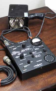
The next evolutionary step in performing rotor blade track and balance is a Chadwick-manufactured system called the model 177. Even today, I still hear other brands of track-and-balance equipment called a Chadwick. Jim Chadwick did the helicopter industry a big favor with his constant desire to improve on his equipment. Sharkey appears to be one of Chadwick’s biggest fans. A good number of even Chadwick’s earliest machines are still in service today. This was the first big improvement over the constant light method in that if you had a two-, three- or four-bladed main rotor; it could perform a track on all the blades at the same time. It could also do a balance on the
main rotor and on the tail rotor as well. It can also handle engine rpms up to 99,000.
The bad news is that compared to today’s newer systems, the Model 177 is analog and uses older technology. It does not perform spectrum analysis, it would easily get out of calibration, does not print out results, and it hates any kind of moisture. To properly use this system on a piston-powered helicopter or one without a governor (back
then, what was a governor?), the Chadwick operator and pilot must work together. If the rotor speed is allowed to vary due to wind gusts or inattention, then the results will change if not caught and corrected by the operator. This is naturally undesirable. All in all, however, it was a large leap in the right direction.
Chadwick Model 192
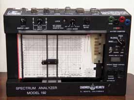 Then that great helicopter mechanic in the sky smiled down on us and the next evolution in track-and-balance test equipment was the Chadwick Model 192 spectrum analyzer. This was a giant step forward in its day. This machine was loved by some and hated by others. There are many mechanics today that swear by the Model 192. By using the term “spectrum analyzer,” Chadwick was saying that the Model 192 would show the peak frequency of everything that is vibrating on the helicopter, from the most to the least vibration. By determining the frequency of the vibration, it would give the mechanic the ability to see if he or she had a one-per-rev, two-per-rev or three-per-rev of a particular frequency. By doing some research, the mechanic could determine which component or system was causing the vibration. Being able to change the color of the pens for each run was a great advertising tool when you gave the customer the read out in color. Back then, anything in color made your work stand out.
The Model 192 measured vibrations by connecting to various points on the helicopter and then the engines and rotor system would be run at 100 percent. The Model 192 incorporated a chart drive that would plot the vibrations on a paper that the mechanic could see. The pen was driven by a rubber belt drive and moved at a constant speed. This was factored into the system to provide the vibration analysis printout. The system did not give the mechanic any corrective action to take, but it did provide him or her with a tool to help determine where to start looking for the problem. This also provided a means to show the customer what the vibration level was when the helicopter was brought in for maintenance, and what the vibration level was once the problem was solved. Keep in mind that customers love fancy, equipment-generated paper with understandable and positive results!
As with all systems, there are pros and cons. We have mentioned the pros. The cons, although not numerous, were there none the less. The biggest one is if you are not done using the machine and leave it in the helicopter and forget to turn it upside down and cover it, you won’t make that mistake again. The sun really does a number on the rubber bands and pens. The other con was that when the Model 192 first came on the market, there was no such thing as a loaner pool when it required a trip back to the factory. If you were a small operator, you could not afford to buy two of them. When the Model 192 was sent back to Chadwick for service, it took quite some time to get the unit repaired and returned. This left you hurting for a bit.
Chadwick Model 8500
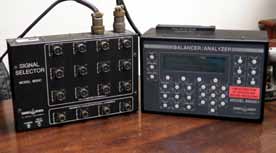
The fourth and probably largest step (much of its technology is still in use today) in the evolutionary ladder of track-and-balance fixtures brings us into the realm of digital technology with the Chadwick Model 8500. This unit is smaller, lighter and has more capability than its predecessors. This was a huge leap forward in not only determining the source of the vibratory problem, but in its ability to check track and balance throughout the helicopter’s entire flight envelope. It would then offer a customizable solution which was sent to an onboard printer. The Model 8500 takes the best features of earlier track-and-balance fixtures and improves upon them. Trying to see changes measured in millimeters with our eyes is difficult. The Model 8500 includes an optical tracker (camera), which allows the mechanic to also see blade spread and lead and lag data. The Model 8500 provides real time numbers and again, we can show our customers what their helicopter’s vibration condition is before and after maintenance is performed.
The pros we have just touched on a few of the major ones, and there are many more. All in all, this is a nice piece of equipment. The cons are that the Model 8500 comes with a pretty hefty price tag and takes longer to acquire that first run data. It does a lot more and to do more, it looks at more data and takes longer in doing so. This translates into more run time for the customer’s helicopter and that costs more money. I believe this is a small price to pay for the excellent results that are achieved from the Model 8500.
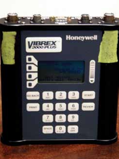
Chadwick Vibrex 2000 Plus
As we continue down the evolutionary path of track-and-balance test equipment, we come to the Chadwick Vibrex 2000 Plus. This is also a digital unit so it is small, lightweight and quick and easy to install. Its cost is affordable and it has its own self-contained power supply. It also has a battery-operated portable printer option that can be purchased off the Web for almost free, as helicopter tools go. Another great feature is a built-in memory, so the track-and-balance information can be stored and printed at a later time and place. The unit is “bullet proof” to rain and snow. Sharkey said they got one of the very first Model 2000 units, it was not even a Plus, and it has never gone back to the factory for any repair. It still works as expected! The Vibrex 2000 Plus uses an electric eye or magnetic interrupter to see the master rotor blade and velocimeters to determine the amount of out of track or balance which is read out on a display.
Talking with Sharkey, the only con he observes with the Chadwick Vibrex 2000 Plus is with complex rotor systems. By complex, Sharkey says he is talking about a four- or five-bladed system. In most two- and three-bladed rotor systems, the balance is checked in a hover. To correct the balance, either the blade is swiped and/or lead fishing shot is added as required. There is a paper chart to help determine how much weight or sweep is needed. The balance is then checked again. If the balance is good, you then proceed to flight tracking the blades. Blade track has a big effect on blade balance, but balance does not have a large effect on track. That is why balance is performed first.
In complex rotor systems, balance is also used to help control the lead and lag of the blade. If the system is out of balance, then the blade dampers have to work overtime to try to keep the rotor system in balance. This is why blade match is so important when you move beyond a two-bladed rotor system. Each blade must be balanced and tracked individually, but must fly together for the whole system to work in harmony. This equates to more adjustments to be made, which calls for more run time on the helicopter, with more cost to the operator.
According to Sharkey, “The 2000+ is the best bang for the buck in tracking and balancing simple rotor systems.”
Chadwick/Honeywell VXP Acquisition Unit & Lap Top
The last unit in our litany is the Chadwick/Honeywell VXP acquisition unit. It does everything all the predecessors did and then some — but 10 times better and four times faster! As with the 8500+, there are no paper charts or guessing how much — all of this is done for you. You also have the ability to display data on any Windows-based PC. Sharkey says the best part is that you can change a parameter such as fewest adjustments, best track, best balance, track and balance, or even drop one of the fields you acquired because they just don’t add up and you think that they may be skewing your solution. An example might be 60Kts let down and ask it to give you a new prediction. If this does not work, you can just put it back in. The VXP system will send the change to the acquisition unit, which in turn does new computations and sends the new data for PC display.
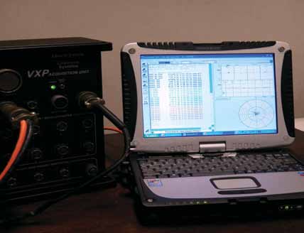
This unit does it all: track, balance, lead and lag, and trend monitoring. It even has a program to check all the other rotating components. Complex rotor systems are handled with ease.
“I have tried many different kinds of track and balance systems, we even ran the VXP and brand X on the same helicopter at the same time so we could get a real feel for which one was actually better,” says Sharkey. “The VXP beat the other system badly! I personally believe that the VXP is the best track-and-balance system ever built — period.”
At the time of this writing, Sharkey and I were hopeful to add the Honeywell Zing Elite portable diagnostic test set to our list of track-and-balance test equipment, but it was not yet available for our evaluation.
From the past to the present, there has always been a need to track and balance a helicopter’s rotor system. The tools available to do this changed with the times and went from analog to digital and became computerized along the way. Many thanks to Sharkey for providing his insight on the progression of Chadwick track-and-balance test equipment. While there are other manufacturers out there that manufacture track-and-balance equipment, this article discussed only Chadwick equipment because it’s what Sharkey uses and knows best.It is meant as a way to see the evolution of equipment through the experience of one user with one manufacturer.
Tracking and balancing helicopter rotor systems is not an exact science, but rather a slowly-acquired art form that is developed over time. I am a big believer in the saying, “you can teach from experience, but you cannot teach experience.”
For more information on track and balance, see the February/March 2012 issue of HeliMx, or visit our Web site at www.helimx.com.